 |  |
|  | |||||||


| Electromagnetism By Sir Tariq Bhatti |
| | Thread Tools | Search this Thread | Rating:  | Display Modes |


|
#1
 05-09-2008, 03:14 AM
| ||||
| ||||
| If two or more circuit components are connected end to end like a daisy chain, it is said they are connected in series. A series circuit is a single path for electric current through all of its components. If two or more circuit components are connected like the rungs of a ladder it is said they are connected in parallel. A parallel circuit is a different path for current through each of its components. A parallel circuit provides the same voltage across all its components. An old term for devices connected in parallel is multiple, such as a multiple connection for arc lamps. As an example, consider a very simple circuit consisting of four light bulbs and one 6 V battery. If a wire joins the battery to one bulb, to the next bulb, to the next bulb, to the next bulb, then back to the battery, in one continuous loop, the bulbs are said to be in series. If each bulb is wired to the battery in a separate loop, the bulbs are said to be in parallel. If the four light bulbs are connected in series the same current flows in all of them; each light bulb experiences about 1.5 V. If two light bulbs are connected in parallel, the currents flowing through the two light bulbs combine to form the current flowing in the battery; each light bulb experiences 6 V. In a series circuit, every device must function. A set of light bulbs in series with one bulb burning out, kills the circuit. In parallel, every light has its own circuit, so all but one light could be burned out, and the last one will still illuminate. Series circuits Series circuits are sometimes called current-coupled or daisy chain-coupled. The current that flows in a series circuit has to flow through every component in the circuit. Therefore, all of the components in a series connection carry the same current. It has been noted that current flows in series.To find the total resistance of all the components, add the individual resistances of each component:   . .  where I is the current, as calculated above. The components divide the voltage according to their resistances, so, in the case of two resistors, where I is the current, as calculated above. The components divide the voltage according to their resistances, so, in the case of two resistors, . .Parallel circuits: If two or more components are connected in parallel they have the same potential difference (voltage) across their ends. The potential differences across the components are the same in magnitude, and they also have identical polarities. Hence, the same voltage is applicable to all circuit components connected in parallel. The total current I is the sum of the currents through the individual components, in accordance with Kirchhoff's circuit laws. The current in each individual resistor is found by Ohm's law. Factoring out the voltage gives 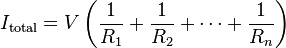 . .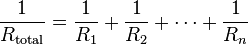 . To find the current in a component with resistance Ri, use Ohm's law again: . To find the current in a component with resistance Ri, use Ohm's law again: . The components divide the current according to their reciprocal resistances, so, in the case of two resistors, . The components divide the current according to their reciprocal resistances, so, in the case of two resistors, . .
__________________ (¯`v´¯) `*.¸.*` ¸.*´¸.*´¨) ¸.*´¨) (¸.*´ (¸.Bzu Forum   Don't cry because it's over, smile because it happened Don't cry because it's over, smile because it happened   |

 .BZU.
.BZU.


| Tags |
| circuits, lectures, parallel, series |
« Previous Thread
|
Next Thread »
| Currently Active Users Viewing This Thread: 1 (0 members and 1 guests) | |


 Threaded Mode
| |

 Similar Threads
 | ||||
| Thread | Thread Starter | Forum | Replies | Last Post |
| chapter#18: Parallel pr0cessing... | hurain07 | Computer Architecture | 0 | 11-07-2011 07:06 PM |
| Phasor diagram solution of AC circuits. | bonfire | Electrical Circuits | 0 | 17-04-2011 01:25 AM |
| DC Circuits Presentation. | bonfire | Electrical Circuits | 0 | 17-04-2011 12:04 AM |
| DC Circuits with Practical Examples. | bonfire | Electrical Circuits | 0 | 16-04-2011 11:59 PM |
| Chapter 14: Feedback and Oscillator Circuits | bonfire | Electrical Circuits | 0 | 19-03-2011 08:10 PM |
Almuslimeen.info | BZU Multan | Dedicated server hosting
Note: All trademarks and copyrights held by respective owners. We will take action against any copyright violation if it is proved to us.
All times are GMT +5. The time now is 01:12 AM.
Powered by vBulletin® Version 3.8.2
Copyright ©2000 - 2026, Jelsoft Enterprises Ltd.
Copyright ©2000 - 2026, Jelsoft Enterprises Ltd.