 |  |


|
#1
 17-04-2011, 01:33 AM
| ||||
| ||||
| Three-phase electric power  Three-phase electric power is a common method of alternating current electric power generation, transmission, and distribution.[1] It is a type of polyphase system and is the most common method used by grids worldwide to transfer power. It is also used to power large motors and other large loads. A three-phase system is generally more economical than others because it uses less conductor material to transmit electric power than equivalent single-phase or two-phase systems at the same voltage.[2] The three-phase system was introduced and patented by Nikola Tesla in the years from 1887 to 1888. In a three-phase system, three circuit conductors carry three alternating currents (of the same frequency) which reach their instantaneous peak values at different times. Taking one conductor as the reference, the other two currents are delayed in time by one-third and two-thirds of one cycle of the electric current. This delay between phases has the effect of giving constant power transfer over each cycle of the current and also makes it possible to produce a rotating magnetic field in an electric motor. Three-phase systems may have a neutral wire. A neutral wire allows the three-phase system to use a higher voltage while still supporting lower-voltage single-phase appliances. In high-voltage distribution situations, it is common not to have a neutral wire as the loads can simply be connected between phases (phase-phase connection). Three-phase has properties that make it very desirable in electric power systems:
Most household loads are single-phase. In North America and some other countries, three-phase power generally does not enter homes. Even in areas where it does, it is typically split out at the main distribution board and the individual loads are fed from a single phase. Sometimes it is used to power electric stoves and electric clothes dryers. The three phases are typically indicated by colors which vary by country. See the table for more information. Generation and distribution 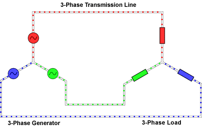  Animation of three-phase current flow 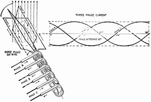  Left: Elementary six-wire three-phase alternator, with each phase using a separate pair of transmission wires.[3] Right: Elementary three-wire three-phase alternator, showing how the phases can share only three wires.[4] Left: Elementary six-wire three-phase alternator, with each phase using a separate pair of transmission wires.[3] Right: Elementary three-wire three-phase alternator, showing how the phases can share only three wires.[4]At the power station, an electrical generator converts mechanical power into a set of three alternating electric currents, one from each coil (a.k.a. "winding") of the generator. The windings are arranged such that the currents vary sinusoidally at the same frequency but with the peaks and troughs of their wave forms offset to provide three complementary currents with a phase separation of one-third cycle (120° or 2π/3 radians). The generator frequency is typically 50 or 60 Hz, varying by country. (See Mains power systems for more detail.) Large power generators provide an electric current at a potential which can be a few hundred volts or up to about 30 kV. At the power station, transformers step this voltage up to one suitable for transmission. After numerous further conversions in the transmission and distribution network, the power is finally transformed to the standard utilization voltage for lighting and equipment. Single-phase loads are connected from one phase to neutral or between two phases. Three-phase loads such as larger motors must be connected to all three phases of the supply. [edit] Three-wire versus four-wire Three-phase circuits occur in two varieties. In one case, there are only three energized ("hot") wires; in the other case, there are three hot wires plus a neutral wire. Four-wire circuits offer flexibility, since a load may be connected "line-to-line" or "line-to-neutral"; three-wire circuits offer economy, since the neutral conductor is eliminated. Commonly, distribution voltage circuits are four-wire, while higher voltage transmission circuits are three-wire. Transmission lines often figure a ground wire, but this is solely for lightning protection and is not connected to deliver electrical power. [edit] Single-phase loads Single-phase loads may be connected to a three-phase system in two ways. Either a load may be connected across two of the live conductors, or a load can be connected from a live phase conductor to the neutral conductor. Single-phase loads should be distributed evenly between the phases of the three-phase system for efficient use of the supply transformer and supply conductors. If the line-to-neutral voltage is a standard load voltage, for example 230 volt on a 400 volt three-phase system, single-phase loads can connect to a phase and the neutral. Loads can be distributed over three phases to balance the load. Where the line-to-neutral voltage is not the standard voltage for example 347 volts produced by a 600 V system, single-phase loads are connected through a step-down transformer. In a symmetrical three-phase system, the system neutral has the same magnitude of voltage to each of the three-phase conductors. The voltage between line conductors (Vl) is √3 times the phase conductor to neutral voltage (Vp). That is: Vl = √3Vp. In some multiple-unit residential buildings of North America, three-phase power is supplied to the building but individual units have only single-phase power formed from two of the three supply phases. Lighting and convenience receptacles are connected from either phase conductor to neutral, giving the usual 120 V required by typical North American appliances. In the split-phase system, high-power loads are connected between the opposite "hot" poles, giving a voltage of 240 V. In some cases, they may be connected between phases of a three-phase system, giving a voltage of 208 V. This practice is common enough that 208 V single-phase equipment is readily available in North America. Attempts to use the more common 120/240 V equipment intended for split-phase distribution may result in poor performance since 240 V heating and lighting equipment will only produce 75% of its rating when operated at 208 V. Motors rated at 240 V will draw higher current at 208 V; some motors are dual-labelled for both voltages. Where three-phase at low voltage is otherwise in use, it may still be split out into single-phase service cables through joints in the supply network or it may be delivered to a master distribution board (breaker panel) at the customer's premises. Connecting an electrical circuit from one phase to the neutral generally supplies the country's standard single phase voltage (120 V AC or 230 V AC) to the circuit. The currents returning from the customers' premises to the supply transformer all share the neutral wire. If the loads are evenly distributed on all three phases, the sum of the returning currents in the neutral wire is approximately zero. Any unbalanced phase loading on the secondary side of the transformer will use the transformer capacity inefficiently. If the supply neutral of a three-phase system with line-to-neutral connected loads is broken, the voltage balance on the loads will no longer be maintained. The neutral point will tend to drift toward the most heavily loaded phase, causing undervoltage conditions on that phase only. Correspondingly, the lightly loaded phases may approach the line-to-line voltage, which exceeds the line-to-neutral voltage by a factor of √3, causing overheating and failure of many types of loads. For example, if several houses are connected through a 240 V transformer, which is connected to one phase of the three-phase system, each house might be affected by the imbalance on the three phase system. If the neutral connection is broken somewhere in the system, all equipment in a house might be damaged due to over-voltage. A similar phenomenon can exist if the house neutral (connected to the center tap of the 240 V pole transformer) is disconnected. This type of failure event can be difficult to troubleshoot if the drifting neutral effect is not understood. With inductive and/or capacitive loads, all phases can suffer damage as the reactive current moves across abnormal paths in the unbalanced system, especially if resonance conditions occur. For this reason, neutral connections are a critical part of a power distribution network and must be made as reliable as any of the phase connections. Where a mixture of single-phase 120-volt lighting and three-phase, 240-volt motors are to be supplied, a system called high-leg delta is used. [edit] Three-phase loads A transformer for a high-leg delta system; 240 V 3-phase motors would be connected to L1, L2 and L3. Single-phase lighting would be connected L1 or L2 to neutral (N). No loads would be connected from L3 (the high or wild leg) to neutral, since the voltage would be 208 V. The most important class of three-phase load is the electric motor. A three-phase induction motor has a simple design, inherently high starting torque and high efficiency. Such motors are applied in industry for pumps, fans, blowers, compressors, conveyor drives, electric vehicles and many other kinds of motor-driven equipment. A three-phase motor is more compact and less costly than a single-phase motor of the same voltage class and rating and single-phase AC motors above 10 HP (7.5 kW) are uncommon. Three-phase motors also vibrate less and hence last longer than single-phase motors of the same power used under the same conditions. Resistance heating loads such as electric boilers or space heating may be connected to three-phase systems. Electric lighting may also be similarly connected. These types of loads do not require the revolving magnetic field characteristic of three-phase motors but take advantage of the higher voltage and power level usually associated with three-phase distribution. Legacy fluorescent lighting systems also benefit from reduced flicker if adjacent fixtures are powered from different phases. Large rectifier systems may have three-phase inputs; the resulting DC is easier to filter (smooth) than the output of a single-phase rectifier. Such rectifiers may be used for battery charging, electrolysis processes such as aluminium production or for operation of DC motors. An interesting example of a three-phase load is the electric arc furnace used in steelmaking and in refining of ores. In much of Europe, stoves are designed for a three-phase feed. Usually the individual heating units are connected between phase and neutral to allow for connection to a single-phase supply. In many areas of Europe, single-phase power is the only source available. Phase converters Occasionally the advantages of three-phase motors make it worthwhile to convert single-phase power to three-phase. Small customers, such as residential or farm properties, may not have access to a three-phase supply or may not want to pay for the extra cost of a three-phase service but may still wish to use three-phase equipment. Such converters may also allow the frequency to be varied allowing speed control. Some railway locomotives are moving to multi-phase motors driven by such systems even though the incoming supply to a locomotive is nearly always either DC or single-phase AC. Because single-phase power goes to zero at each moment that the voltage crosses zero but three-phase delivers power continuously, any such converter must have a way to store energy for the necessary fraction of a second. One method for using three-phase equipment on a single-phase supply is with a rotary phase converter, essentially a three-phase motor with special starting arrangements and power factor correction that produces balanced three-phase voltages. When properly designed, these rotary converters can allow satisfactory operation of three-phase equipment such as machine tools on a single-phase supply. In such a device, the energy storage is performed by the mechanical inertia (flywheel effect) of the rotating components. An external flywheel is sometimes found on one or both ends of the shaft. A second method that was popular in the 1940s and 1950s was the transformer method. At that time, capacitors were more expensive than transformers, so an autotransformer was used to apply more power through fewer capacitors. This method performs well and does have supporters, even today. The usage of the name transformer method separated it from another common method, the static converter, as both methods have no moving parts, which separates them from the rotary converters. Another method often attempted is with a device referred to as a static phase converter. This method of running three-phase equipment is commonly attempted with motor loads though it only supplies ⅔ power and can cause the motor loads to run hot and in some cases overheat. This method does not work when sensitive circuitry is involved such as CNC devices or in induction and rectifier-type loads. Some devices are made which create an imitation three-phase from three-wire single-phase supplies. This is done by creating a third "subphase" between the two live conductors, resulting in a phase separation of 180° − 90° = 90°. Many three-phase devices can run on this configuration but at lower efficiency. Variable-frequency drives (also known as solid-state inverters) are used to provide precise speed and torque control of three-phase motors. Some models can be powered by a single-phase supply. VFDs work by converting the supply voltage to DC and then converting the DC to a suitable three-phase source for the motor. Digital phase converters are designed for fixed-frequency operation from a single-phase source. Similar to a variable-frequency drive, they use a microprocessor to control solid-state power switching components to maintain balanced three-phase voltages. Alternatives to three-phase
__________________    |

 bonfire


 |
| Tags |
| electric, power, threephase |
« Previous Thread
|
Next Thread »
| Currently Active Users Viewing This Thread: 1 (0 members and 1 guests) | |
 Linear Mode

| |

 Similar Threads
 | ||||
| Thread | Thread Starter | Forum | Replies | Last Post |
| 10% Overseas Scholarships for PhD in Selected Fields Phase-II, Batch-7 | .BZU. | Daily News And halat-e-hazra | 0 | 23-07-2011 08:22 PM |
| Comment regarding load shedding/Electric power cut off in Pakistan | .BZU. | Youtube Videos/Clips etc | 0 | 24-05-2011 04:15 AM |
| Single-phase electric power | bonfire | Electrical Circuits | 0 | 17-04-2011 01:29 AM |
| Swine flu epidemic enters dangerous new phase | BSIT07-01 | Daily News And halat-e-hazra | 1 | 28-04-2009 12:36 PM |
Almuslimeen.info | BZU Multan | Dedicated server hosting
Note: All trademarks and copyrights held by respective owners. We will take action against any copyright violation if it is proved to us.
All times are GMT +5. The time now is 08:35 AM.
Powered by vBulletin® Version 3.8.2
Copyright ©2000 - 2026, Jelsoft Enterprises Ltd.
Copyright ©2000 - 2026, Jelsoft Enterprises Ltd.